Why Does an Industrial CNC Router Spindle Experience Thermal Overload, and How to Troubleshoot It?
An expert engineering Q&A manual detailing why industrial CNC spindles experience thermal overload trips and how to calibrate VFD current parameters.

In automated manufacturing, rapid aerospace prototyping, and heavy-duty sheet fabrication corridors, the high-speed electro-spindle is the definitive mechanical node driving continuous production. Operating at extreme rotational velocities (frequently spanning 18,000 to 24,000 RPM), the spindle spindle assembly uses built-in AC servo or induction motors to handle high torsional cutting resistances across aluminum alloys, engineered plastics, and dense timber blocks.Because the cutting envelope is flooded with fine composite dust, microscopic metal shards, and thermal friction vectors, maintaining strict temperature profiles inside the spindle housing is critical.When a CNC machine logs an erratic thermal spike, a variable-frequency drive (VFD fieldbus fault), or triggers an unexpected spindle thermal overload trip, the event halts production. This risk path introduces structural bearing seizure threats, localized winding insulation destruction, and catastrophic shaft distortion failures, costing precision manufacturing facilities thousands of dollars in scrapped workpieces and structural rebuilding fees.This engineering operations manual breaks down the thermodynamic root causes of electro-spindle overheating, sets strict operational limits, and outlines a step-by-step diagnostic sequence to protect your high-speed automated nodes.
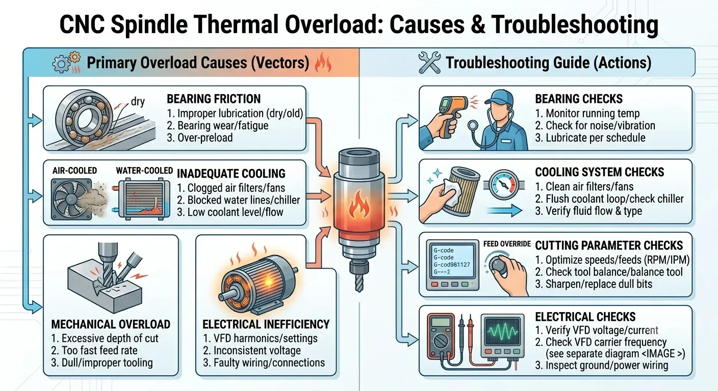
The 4 Primary Root Causes of Spindle Thermal Overloads
When the centralized digital SCADA operator desk or the handheld industrial CNC controller registers an active thermal error loop, field automation technicians must isolate four independent sub-systems.

1. Liquid-Cooling Chiller Circuit Scale Encrustation & Flow Starvation
High-power CNC electro-spindles rely on a continuous closed-loop industrial water or oil chiller system to pull heat away from the internal stator windings.
- The Thermodynamic Failure: Over long operating schedules, un-distilled water or low-grade coolant fluids form a dense calcium carbonate scale along the narrow internal cooling channels of the aluminum spindle jacket. This mineral layer traps heat inside the motor windings. If the chiller pump experiences an internal seal blow-by or fluid starvation, the volumetric flow rate drops, causing immediate thermal runaway inside the spindle frame.
2. Excessive VFD Carrier Frequency Harmonic Heating
The rotational velocity of the electro-spindle is governed by a digital Variable Frequency Drive (VFD).
- The Electrical Signal Fault: If the maintenance team configures the VFD's carrier frequency parameters incorrectly (e.g., setting it too low to bypass electrical noise), the VFD generates severe harmonic distortions and high ripple current loops. These eddy currents leak directly into the spindle's copper stator windings, generating high electrical heat dissipation fields that easily overpower standard fan or liquid-cooling arrays, triggering an insulation grounding failure.
3. Precision Ceramic Bearing Clearance Fatigue & Tribological Breakdown
To operate smoothly at 24,000 RPM, modern premium spindles utilize high-precision P4-grade hybrid ceramic ball bearings locked under specific factory axial pre-loads.
- The Wear Mechanism: If aggressive cutting feed rates introduce un-symmetric axial shock loads, or if fine composite stone dust passes the primary front air-purge labyrinth seals, the lubrication film breaks down. The hybrid ceramic balls experience boundary friction, flattening their micro-geometry and generating high frictional heat that distorts the main shaft alignment.
4. Excessive Mechanical Tool-Engagement Duty Cycles (Over-Cutting)
- The Kinetic Overload: Pushing a CNC router to execute aggressive depth-of-cut profiles using dull solid-carbide router bits forces the spindle to run at maximum amperage limits for extended periods. This continuous high current draw quickly breaks down the copper winding insulation, causing an immediate phase-to-phase current imbalance that triggers the VFD's automated overload protection relays.
Technical Specifications & Spindle Thermodynamic Tolerances
The specification matrix below outlines the strict physical dimensions, electrical settings, and fluid parameters required to maintain optimal high-speed CNC spindle performance.
| Operational Parameter / Node Axis | Standard Target Parameter | Critical Fault / Failure Threshold | Precision Measurement Device |
|---|---|---|---|
| Windings Core Operating Temp | 35°C to 48°C (Optimal Duty) | > 60°C (Automation Overload Trip) | Integrated PT100 Thermal Sensor |
| Chiller Fluid Supply Flow Rate | 3.5 to 5.5 L/min | < 2.0 L/min (Volumetric Starvation) | Inline Turbine Flow Sensor |
| VFD Output Carrier Frequency | 8.0 kHz to 12.0 kHz | < 4.0 kHz (Severe Harmonic Overheat) | Digital Oscilloscope Analyzer |
| Winding Insulation Resistance | ≥ 500 MΩ (Mega-Ohms) | < 20 MΩ (Windings Ground Short) | High-Voltage Digital Megger |
| Front Air-Purge Labyrinth Pressure | 0.15 MPa to 0.25 MPa (1.5-2.5 bar) | < 0.10 MPa (Dust Ingress Risk Active) | Precision Air Pressure Regulator |
Step-by-Step Spindle Diagnostics & Remediation Sequence
When a VFD thermal fault or motor current overload registers on the CNC interface, maintenance crews must execute this structured repair path immediately:
Step 1: Enforce Complete Kinetic & Electrical Isolation
- Disengage the main circuit breaker on the CNC electrical enclosure door. Enforce strict Lockout-Tagout (LOTO) protocols on the factory electrical master terminal.
- Ensure the spindle shaft has decelerated to a complete stop before opening the primary safety gantry shielding.
- Allow the spindle housing to sit idle for 15 minutes to cool down, preventing severe skin burn hazards during manual inspection.
Step 2: Clear Chiller Core Scales and Reset Volumetric Flow Lines
If the spindle housing is hot to the touch but the external chiller unit displays a normal temperature:
- Unbolt the quick-connect fluid input and output polyurethane hoses from the top of the electro-spindle frame.
- Attach a manual pressure pump filled with an industrial-grade organic descaling solvent to the spindle's input cooling port.
- Engineering Remediation: Flush the solvent through the internal cooling jacket for 20 minutes to strip away mineral scaling caked onto the water lines. Flush the jacket with distilled water, re-verify that your chiller pump outputs a clean 4.5 L/min flow velocity, and secure the hose clamps to eliminate air-lock blockages.
Step 3: Calibrate the VFD Overload Relays and Test Insulation Resistance
If the chiller loop is clear but the VFD continues to trip during light cutting sequences:
- Open the primary electrical enclosure. Disconnect the main U, V, and W spindle motor output lines from the VFD terminal blocks.
- Hook up a digital megohmmeter. Test the insulation resistance between Phase U and the outer ground chassis frame.
- Diagnostic Inference: If the multimeter registers beneath 50 MΩ, the internal stator insulation has suffered permanent thermal degradation; the spindle must be sent out for robotic rewinding. If insulation passes above 500 MΩ, access the VFD parameter menu, navigate to the Electronic Thermal Overload Relay Constant (Parameter Motor FLA), and ensure the current rating matches the exact nameplate amperage stamped on the spindle casing.

FAQ
Q1: Why should an aerospace procurement manager specify dual-angle matched contact ceramic bearings instead of standard steel ball bearings for high-speed CNC spindles?
A1: Sourcing directors must prioritize material engineering parameters when finalizing a high-speed CNC spindle replacement parts contract. Standard steel ball bearings experience massive centrifugal forces and severe friction changes when operating past 15,000 RPM, causing rapid lubrication breakdown and thermal expansion tracking errors that seize the main shaft. Mandating matched pairs of P4-grade Angular Contact Hybrid Ceramic Ball Bearings (utilizing Silicon Nitride Si₃N₄ balls) significantly drops operational expenditures (OPEX). Ceramic balls are 60% lighter than steel, generate negligible thermal expansion vectors, and provide an exceptionally low friction coefficient. This upgrade cuts bearing operating temperatures by half and expands the component operating lifespan past 8,000 continuous cutting hours, maximizing factory ROI.
Q2: How does an integrated positive air-purge labyrinth seal protect high-value electro-spindles from early winding failures?
A2: High-speed cutting sequences across carbon-fiber panels or resin-infused hardwoods generate highly abrasive, micro-fine dust clouds. Standard mechanical rubber contact lip seals fail under 18,000 RPM friction speeds, hardening and letting fine particles pass straight into the front bearing race. Mandating a spindle configured with an integrated continuous positive air-purge labyrinth seal (injecting clean, dry instrument air at a continuous 0.20 MPa) creates an outbound air barrier. This continuous positive air pressure blocks airborne dust from entering the bearing cavity, entirely preventing bearing pitting and protecting the inner stator windings from tracking grounding shortages.
Request Technical Blueprints & Factory Quotes
Submit your machinery parameters below. Connect directly with verified, certified heavy industrial manufacturers to receive custom foundation drawings, layout schematics, and direct-from-factory pricing.